P3 LCD Display Module Installation
This page is an update on the previous LCD install instructions found here.
There are two variations in the production P3 mounting points for the PLED display.
On the first batch of cases, the lower two mounting posts were positioned incorrectly by the factory, so only the upper two mounting screws can be installed.
This is still enough to hold the display securely.
On early units, there is also a slight overlap of the function key board with the PLED module, as shown here:
If you have an over-lapping function key board, then it will need to be filed down to allow the LCD module to fit, as shown here:
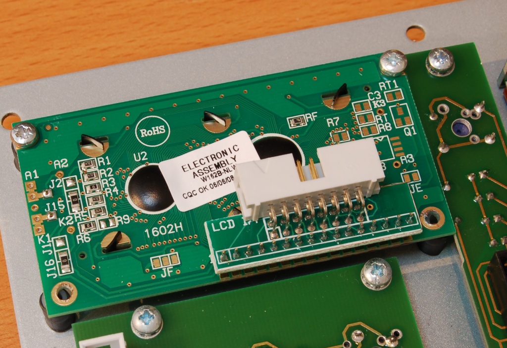
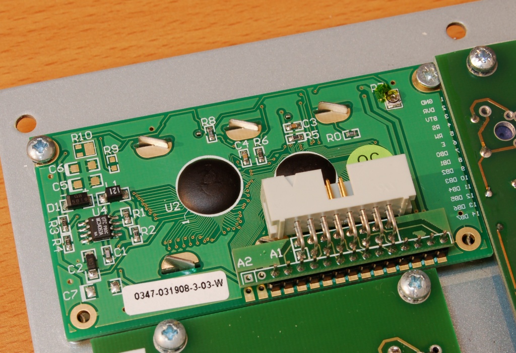
The revised hardware for fitting an LCD display module consists of plastic spacers (to fit on top of the original mounting posts), and longer mounting screws.
After removing the PLED display, fit the spacers over the mounting posts like this:
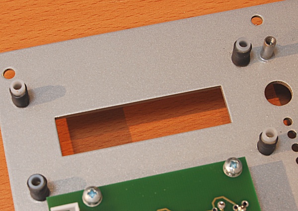
The heat-shrink tubing should hold the spacers in place to allow the screws to be inserted easily.
If you are only using two screws, you should still fit the spacers on the lower posts to ensure the board sits parallel with the panel.
Remember also to install the resistor in position R19 on the P3 mainboard.