Before installing the board, I recommend a slight change to the 303 PSU circuit.
There is a current limiting resistor in the PSU, which can cause the 12v power supply rail to become unstable in some 303s with the small extra current required by the MIDIBass board.
This resistor can be safely replaced wtih a wire link to ensure you don't suffer from this.
The problem can be heard as a 'fluttering' of the filter cutoff as notes are triggered.
The resistor to replace is R172, which can be found just to the right of the VOLUME pot.
I replace it with the leg clipped from one of the resistors used in the SYNC connections.
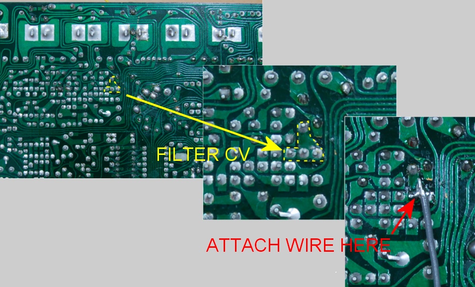
Filter CV Connection
The filter CV connection requires a single wire to be connected to a point in the filter CV mixer circuit on the reverse side of the board.
Connect the wire to the junction of R63, R72 and R71 and Q10.
The wire is routed around the front edge of the main PCB.
This image shows the connection point location, close-up, and with the wire attached:
Fitting the Board
With all the board mods complete, you are now ready to plug in the MIDIBass board.
It's a tight fit, given the minimal available space, but it can be done.
To reduce the chance that the pressure of inserting the board may cause a fracture in the main PCB, it's a good idea to support the PCB with a piece of wood or a book directly under the 16 pins of the socket.
It's important to note that the ribbon cable connection from the switchboard to the mainboard must be run UNDERNEATH the MIDIBass board. It may also need to be pushed to the side slightly to allow the header to be inserted into the 16 pin socket.
Be very careful when you insert the MIDIBass board into its socket not to bend any of the header pins.
Some of the other ribbon cables may need to have their positions adjusted slightly to make room for the MIDIBass wiring.
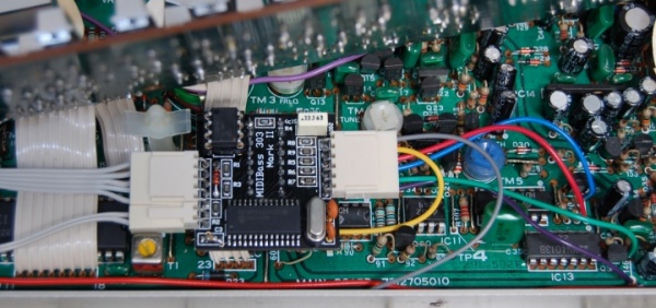
When fitted, it should look like this:
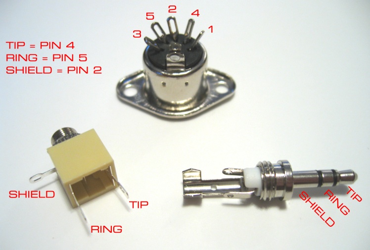
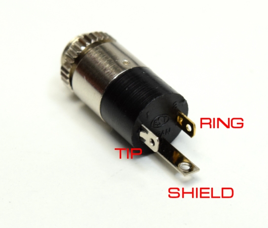
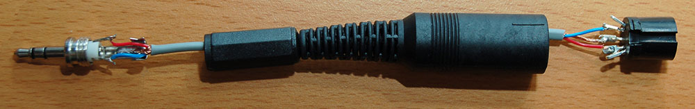
I use pig-tails wired up as shown here (with the soldering all done but the plug covers removed):
By using 3.5mm sockets, the MIDI connections can be fitted to the rear of the 303 case, between the knobs, in the location usually used to fit CV/Gate input sockets. In fact, if you've already fitted a CV input mod kit to your 303, it's likely that you can replace the CV/Gate input sockets with the MIDI In and Out connections without the need to do any futher drilling.
303 Sync Socket As MIDI IN/OUT
If you can live without the 303's DIN SYNC socket, it can be re-purposed for combined MIDI IN and OUT without requiring any additional holes.
The normal MIDI pins are used for the MIDI IN connection.
The outer pins of the socket are used for MIDI out.
For MIDI IN, you need to remove resistors R182 and R29 from the 303 mainboard.
R182 is directly to the left of the SYNC socket.
R29 is the second resistor to the right of the SYNC socket.
Then you can solder the wires for MIDI IN pins 4 and 5 to the SYNC socket pins 4 and 5 using the pads from the resistors.
MIDI IN pin 4 goes to the R182 pad nearest the top edge of the PCB MIDI IN pin 5 goes to the R29 pad also nearest the top edge.
You can now use a standard MIDI cable to feed MIDI into the 303.
Note however, that inserting a DIN plug fully into the SYNC socket will disconnect the sync signals internally.
This will stop the 303 sequencer from running.
You can get round this by bypassing the sync connections as described below, or by making up a MIDI cable with the shield cut-down or removed, such that is doesn't operate the switch in the socket.
To enable the Sync port for MIDI OUT is a little more complicated.
You need to CUT the tracks at the points shown in the image below by the RED lines.
Then you need to solder two small pieces of wire to bypass the switch in the DIN socket - this switch normally disconnects internal clock when a lead is inserted.
The jumper wires go where shown by the YELLOW lines.

With the tracks cut and the jumper wires in place, the internal Sync lines will always connect to the MIDIBass and 303 CPU connections.
MIDIBass will switch between input and output mode on these lines automatically - either turning the 303s clock into MIDI clock, or over-riding the internal clock with incoming MIDI clock.
Solder the MIDI OUT wires 4 and 5 to pins 1 and 3 of the SYNC socket.
You do not need to connect the pin 2 connection for MIDI OUT, as pin 2 of the SYNC socket is already connected to the same ground line that it provides.
But don't leave the loose end of the wire floating about inside - use some tape or cut it short..
To use the combined MIDI port you will need a a Y-cable with inline MIDI IN and MIDI OUT a sockets at one end and a common plug at the other.
Pins 4 and 5 from the MIDI IN socket go to pins 4 and 5 of the common plug.
Pins 4 and 5 of the MIDI OUT socket will go to pins 1 and 3 of the common plug.
Pin 2 of the MIDI OUT socket should also go to pin 2 of the common plug.
Once everything is fitted, and tested OK, just close the case back up following the reverse of the disassembly process, watching that none of the new wires get caught in the case screw mounts.
If you have any questions about the installation procedure, just drop me an email.